Clamps block the holes
Multiple holes or edge features make mechanical clamping inconvenient and restrict tool travel.
Our review: pole layout, open tooling zones and repositioning requirements
Magnetic workholding for drilling steel workpieces is useful only when the workpiece has sufficient ferromagnetic contact and the fixture can manage the machining load. This page focuses on drill thrust, breakout clearance and dense hole patterns, rather than a single catalog holding-force rating.
The most useful starting point is the workpiece rather than a headline magnetic-force rating. For drilling, compare tooling plates, steel blocks and dense hole-map fixtures. Confirm drill breakthrough relief, thrust, chip clearance, support and hole access. The outcome may be a standard chuck, a supported custom fixture or a recommendation not to use magnetic holding.
 APPLICATION VIDEO · ADD VERIFIED FOOTAGE
A suitable magnetic system holds a compatible steel workpiece against a prepared contact surface. This can reduce clamps around the cutting area and make repeated positioning easier.
For drilling, the design also needs support near the hole, adequate breakthrough space, and positive stops where cutting forces could move the workpiece. Magnetic holding alone is not a universal substitute for mechanical restraint.
Send us your hole layout and machine details. We can review whether a standard chuck, adapted face or purpose-built fixture is worth evaluating.
For drilling, the fixture must fit the real operating conditions. Check drill breakthrough relief, thrust, chip clearance, support and hole access. Share hole drawing, plate thickness, drill diameter, machine interface and material to identify the right workholding direction rather than selecting from dimensions alone.
Multiple holes or edge features make mechanical clamping inconvenient and restrict tool travel.
Limited contact and poor support may cause movement, deformation or unreliable drilling conditions.
Axial and lateral loads, breakthrough and chip buildup must be considered before selecting a fixture.
Engineering for drilling steel workpieces begins with support beneath holes with relief paths and locating stops. Workpiece geometry and actual machine travel define the fixture outline; the magnetic pole arrangement must then be evaluated within that structure.
Check material, part size, hole layout and the effective contact area.
Plan the magnetic face type, pole layout, positioning stops and support points. For drilling, confirm support, magnetic contact and machine access against the drawing before treating this as a usable configuration.
Review spindle access, coolant flow, chip clearance and drilling load. For drilling, confirm support, magnetic contact and machine access against the drawing before treating this as a usable configuration.
Provide a clear solution direction with layout drawing, recommended configuration and key inspection points.
For drilling steel workpieces, common workpiece categories include fixture plates, steel blocks and repeated drilling patterns. They do not all need the same magnetic face. Each setup should account for its own contact footprint, support requirements and machining envelope.
For a plate with many holes, the fixture layout should account for the full hole map, available contact area and breakthrough zones—not simply cover the entire table with a magnetic face.
 APPLICATION / BLOCK PARTS
Review side access, locating faces and stop arrangement. For drilling, confirm support, magnetic contact and machine access against the drawing before treating this as a usable configuration.
 APPLICATION / THIN PLATES
Plan support under the drill and control distortion risk. For drilling, confirm support, magnetic contact and machine access against the drawing before treating this as a usable configuration.
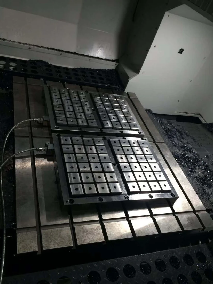 APPLICATION / CUSTOM MACHINE
Match interfaces, clearances and repeated loading needs. For drilling, confirm support, magnetic contact and machine access against the drawing before treating this as a usable configuration.
Engineering for drilling steel workpieces begins with support beneath holes with relief paths and locating stops. Workpiece geometry and actual machine travel define the fixture outline; the magnetic pole arrangement must then be evaluated within that structure.
Machine interfaces, pole arrangements and contact surfaces are considered during the preparation, assembly and finishing process.
Precision machiningMagnetic assemblyFinish grinding
Steel bodies, magnetic materials and related components are prepared for the confirmed fixture design.
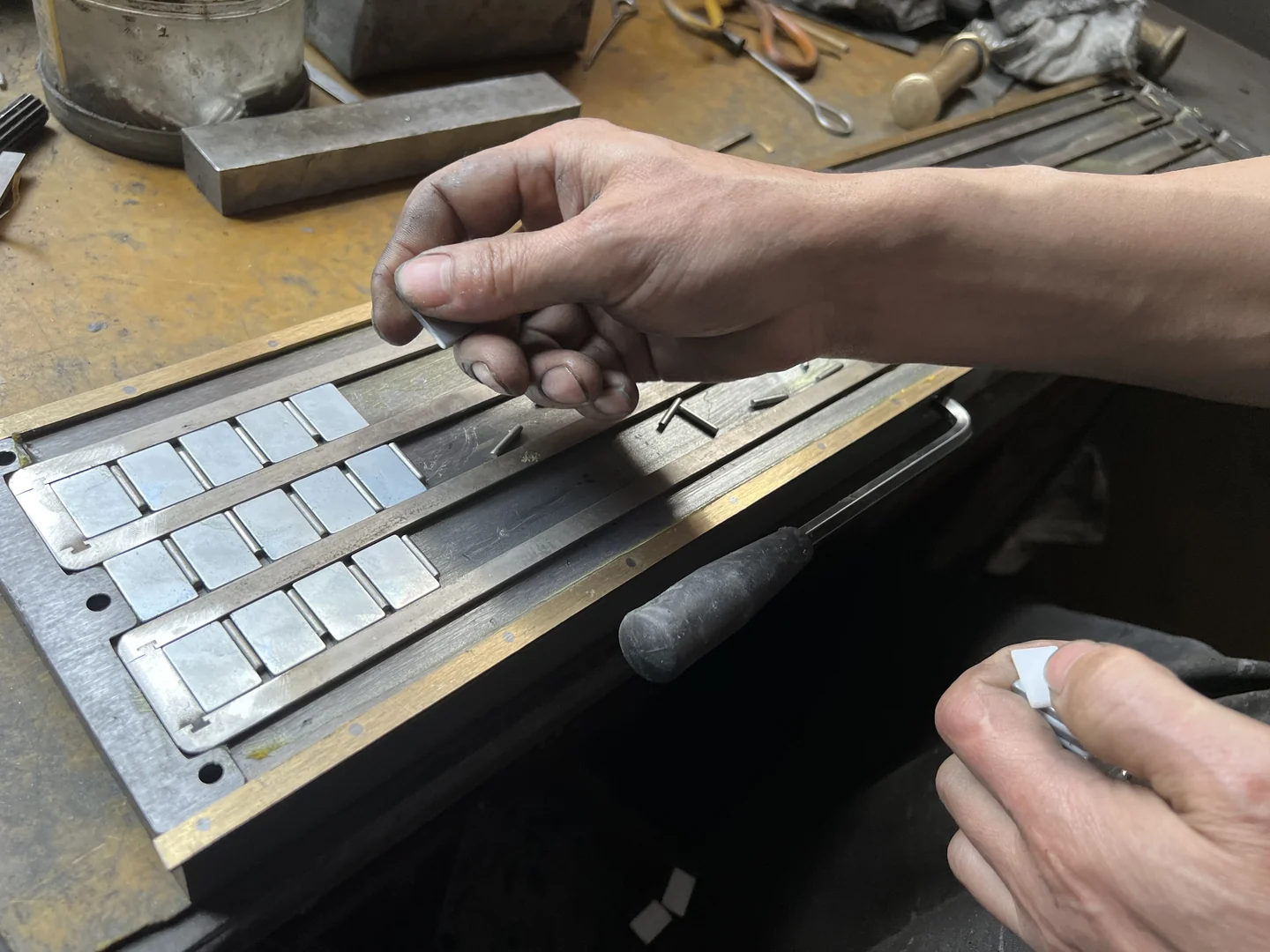
Critical surfaces, mounting features and the magnetic structure are manufactured and assembled.

Grinding and dimensional checks help prepare the surface for the agreed application.
Images are illustrative. Replace with approved workshop images and actual manufacturing records before publication.
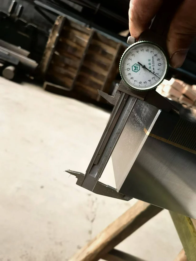 INSPECTION / QUALITY EVIDENCE
Acceptance for drilling steel workpieces should address the installed setup, not just a nominal pull-off figure. In particular, confirm tool clearance, support, stops and holding before actual drilling. Record the actual test conditions and compare them with the agreed application limits.
Send hole drawing, plate thickness, drill diameter, machine interface and material. We can coordinate drawing review, a holding concept, technical confirmation, manufacturing and agreed inspections, followed by protective packaging and relevant operation information. Project dates and documentation depend on the approved scope.
Tell us about your part, machine and drilling task.
Assess contact, clearance, force and feasibility.
Review configuration, stops and interface choices.
Agree on technical and acceptance requirements.
Prepare components for the confirmed design.
Machine, assemble and inspect the fixture.
Protect the finished chuck and prepare documents.
Coordinate operating guidance and technical questions.
Answers to practical drilling steel workpieces fixture questions, including material compatibility, operating limits and the information needed to assess the setup.
Sometimes, provided the underside makes good contact and the design includes adequate support, stops and drill relief.
Provide an approved exit channel or sacrificial support outside the working pole face and check the full drill travel in the setup.
Send hole locations, plate size and grade, drilling loads or tool sizes, machine mounting and desired access zones.
Send material grade, workpiece drawing, maximum and minimum dimensions, hole locations, machine type, drilling conditions, quantity and preferred mounting arrangement.
There is no universal choice. Electro-permanent designs are among the selection directions listed for drilling in the product training material, but suitability still depends on the specific machining setup.
Engineering for drilling steel workpieces begins with support beneath holes with relief paths and locating stops. Workpiece geometry and actual machine travel define the fixture outline; the magnetic pole arrangement must then be evaluated within that structure.