Contact and part size
Review small components, surface coverage and the magnetic circuit. For EDM machining, confirm support, magnetic contact and machine access against the drawing before treating this as a usable configuration.
Magnetic workholding for die-sinking and wire EDM is useful only when the workpiece has sufficient ferromagnetic contact and the fixture can manage the machining load. This page focuses on electrode clearance, flushing and wire path access, rather than a single catalog holding-force rating.
Engineering for die-sinking and wire EDM begins with a magnetic contact zone away from the machining envelope. Workpiece geometry and actual machine travel define the fixture outline; the magnetic pole arrangement must then be evaluated within that structure.

Review the location of the working zone before deciding on the magnetic holding face. For wire EDM, wire travel and flushing clearance are critical; for sinker EDM, electrode access and bath conditions matter.
Engineering for die-sinking and wire EDM begins with a magnetic contact zone away from the machining envelope. Workpiece geometry and actual machine travel define the fixture outline; the magnetic pole arrangement must then be evaluated within that structure.
Review small components, surface coverage and the magnetic circuit. For EDM machining, confirm support, magnetic contact and machine access against the drawing before treating this as a usable configuration.
Leave room for the electrode, wire, flushing nozzles and removed material. For EDM machining, confirm support, magnetic contact and machine access against the drawing before treating this as a usable configuration.
Confirm mounting, operating environment, release and cleaning requirements. For EDM machining, confirm support, magnetic contact and machine access against the drawing before treating this as a usable configuration.
For die-sinking and wire EDM, common workpiece categories include steel mold inserts, tool-steel plates and EDM fixtures. They do not all need the same magnetic face. Each setup should account for its own contact footprint, support requirements and machining envelope.

Design the support and magnetic contact around the required machining region. Check whether the fixture obstructs the electrode or creates an unwanted contact or flushing issue.
Fixture engineering starts with EDM process type, tank size, fluid, workpiece grade and machining path. A workable design needs space for tools and chips while making full use of ferromagnetic contact. Check electrode travel, wire entry/exit, dielectric exposure and unobstructed cutting zones. Confirm dimensions, support points and release method on the drawing before machining the fixture.
Discuss chuck body size, mounting location, pole spacing, stops and the clear machining region. We can coordinate a concept for review before the agreed fabrication and inspection stages.
Electrode / wire
Material suitability
Machine interface
Operating environment

For die-sinking and wire EDM, common workpiece categories include steel mold inserts, tool-steel plates and EDM fixtures. They do not all need the same magnetic face. Each setup should account for its own contact footprint, support requirements and machining envelope.
Keep the electrode, holder and flushing path clear of fixture projections. Review approach direction and the depth of the cavity.
For wire EDM, leave wire threading, cut paths, slug removal and lower-head clearance unobstructed. The fixture must not interfere with wire guides.
Check the dielectric or water-based fluid, immersion level and cleaning method. Confirm whether the selected magnet and seal design is compatible.
Thin parts and narrow contact areas may need backup stops or supplementary fixtures. Confirm whether residual magnetism could affect handling.
APPLICATION REVIEW / TECHNICAL REFERENCEBefore releasing a drawing, record EDM process type, tank size, fluid, workpiece grade and machining path. The fixture sketch should identify magnetic pole coverage, machine mounting, positive stops, tool clearance, coolant exposure and the chosen test conditions. A configuration that fits in CAD still needs practical verification.
Consider full-depth clearance, wire route, cutout support and access from both above and below the workpiece.
Consider pole engagement, repeatable datum surfaces, thermal effects and whether the small footprint needs additional mechanical positioning.
Compare the available systems against the actual operating method: corrosion-resistant and appropriately sealed magnetic workholding after process compatibility checks. Permanent chucks use mechanical magnetic switching, electromagnetic systems depend on continuous coil excitation, and electro-permanent systems use control pulses. Their safety, release and control requirements are not interchangeable.
Confirm table fixing method, EDM type, tank size, fluid chemistry, flushing direction and space for the head or wire guides.
Review corrosion protection, sealing, pole-face condition and any electrical isolation or grounding requirements for the machine.
Define location repeatability, dimensional checks, switching/release function and the actual environmental test conditions where required.
Magnetic workholding is not suitable for every material or operation. Poor ferromagnetic response, inadequate contact, high lateral loads or unsuitable machine conditions can rule it out. Review electrode travel, wire entry/exit, dielectric exposure and unobstructed cutting zones and select an alternative clamp when the required operating margin cannot be demonstrated.
May fit simple ferrous setups where manual activation and release are acceptable and machining access remains clear.
Requires appropriate power and control compatibility. Review heat, wiring, fluid protection and applicable electrical isolation constraints.
Can be considered for switched clamping in compatible systems, subject to actual contact and equipment integration.
Non-magnetic materials, tiny contact areas or restricted wire paths may require mechanical plates, vises or custom supporting structures.
Acceptance for die-sinking and wire EDM should address the installed setup, not just a nominal pull-off figure. In particular, inspect clearance, workface support and machine interface. Record the actual test conditions and compare them with the agreed application limits.
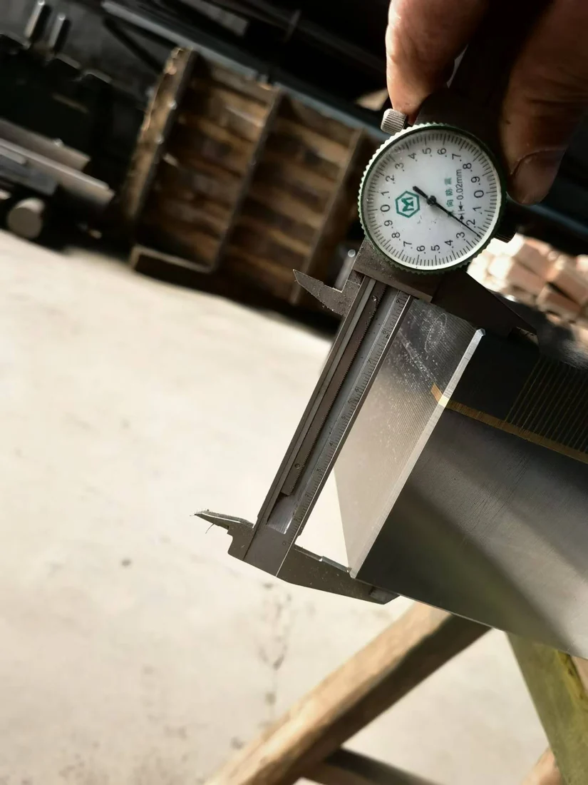
Verification should follow the application and supplied chuck.
Working face and mounting footprint
Correct contact and test method
Fluid, corrosion and process compatibility
Operational checks and cleaning requirements
After choosing a provisional die-sinking and wire EDM fixture, confirm dimensions and acceptance points before production. The shipment should match the approved drawings, with available operating information for the actual magnetic system.
Drawing, material and machine details
Part and process feasibility
Holding structure and selection
Interface and acceptance criteria
Confirmed parts and components
Assembly, surface work and checks
Protective packing and documentation
Use, maintenance and questions
Answers to practical die-sinking and wire EDM fixture questions, including material compatibility, operating limits and the information needed to assess the setup.
Only when the specific chuck is designed for the liquid, electrical and corrosion conditions of the EDM process. Confirm sealing and compatibility.
Not by magnetic attraction alone. Conventional magnetic chucks need a suitable ferromagnetic holding surface.
Confirm the wire path, full-depth cut, slug retention, contact and fluid exposure. Do not allow supports or poles to obstruct the cut.
Engineering for die-sinking and wire EDM begins with a magnetic contact zone away from the machining envelope. Workpiece geometry and actual machine travel define the fixture outline; the magnetic pole arrangement must then be evaluated within that structure.