Concentric placement
Match fixture locating features to the workpiece and spindle.
Magnetic workholding for turning of ferromagnetic circular parts is useful only when the workpiece has sufficient ferromagnetic contact and the fixture can manage the machining load. This page focuses on centrifugal loading, concentricity and rotating mass, rather than a single catalog holding-force rating.
For turning of ferromagnetic circular parts, common workpiece categories include rings, discs and annular steel components. They do not all need the same magnetic face. Each setup should account for its own contact footprint, support requirements and machining envelope.
Match fixture locating features to the workpiece and spindle.
Review rings, thin walls and the seating area.
Confirm speed, balance and retention requirements before use.
These examples show where turning magnetic workholding can be considered for steel discs, rings and suitable round ferromagnetic parts. They are application concepts, not claims about completed customer projects or measured production gains. Each layout requires its own force, contact and safety review.


Engineering for turning of ferromagnetic circular parts begins with a purpose-engineered circular holding face and mechanical location. Workpiece geometry and actual machine travel define the fixture outline; the magnetic pole arrangement must then be evaluated within that structure.

Circular face size, pole layout, locating center, adapter plate, mounting interface and release sequence can form part of the technical design discussion.
Diameter and contact
Locating method
Speed and retention
Machine fit
Workpiece geometry changes the clamping approach. For steel discs, rings and suitable round ferromagnetic parts, begin with spindle arrangement, maximum speed, part mass, ring geometry and machining loads. Check whether contact is continuous, how the tool reaches the surface, and how centrifugal forces, axial contact, balance, centering and positive retention affect fixture design.
Confirm whether the proposed chuck is approved for the required machine speed and axis orientation. Never infer rotational suitability from a static pull-force value.
Uneven rings and eccentric workpieces can create imbalance. Review part mass distribution, centering features and any spindle balancing requirements.
Turning introduces cutting and inertial loads in different directions. Magnetic retention, mechanical location and any backup safety measures must address them.
A thin ring may touch only a narrow area. Check the real contact width, deformation risk, surface condition and the planned unloading method.
APPLICATION REVIEW / TECHNICAL REFERENCEFor turning of ferromagnetic circular parts, common workpiece categories include rings, discs and annular steel components. They do not all need the same magnetic face. Each setup should account for its own contact footprint, support requirements and machining envelope.
Thin walls can distort during machining or handling. Consider support locations and light finishing cuts rather than relying on more nominal holding force.
Through-holes, raised bosses and locating surfaces can interrupt the magnetic face. Review both the mounting side and the tool access above.
Compare the available systems against the actual operating method: only workholding systems explicitly engineered and verified for the rotational setup. Permanent chucks use mechanical magnetic switching, electromagnetic systems depend on continuous coil excitation, and electro-permanent systems use control pulses. Their safety, release and control requirements are not interchangeable.
Define the center bore, registration diameter or pilot, adapter connection and allowable runout for the intended setup.
Record part mass, center of gravity, machine orientation, target spindle speed and machine-maker requirements.
Check how the workpiece is loaded, centered, removed, cleaned and inspected. If suitability cannot be established, recommend a different holding method.
Select the magnetic technology after defining centrifugal loading, concentricity and rotating mass. Compare permanent, electromagnetic and electro-permanent systems by their switching method, control needs, pole design and application limits—not by keyword or chuck size alone.
Mechanical switching can be convenient in some static or approved rotational configurations; obtain the manufacturer’s machine-duty and speed confirmation.
Continuous electrical supply and control arrangements require special attention on rotating equipment. Consult compatible product and machine specifications.
Pulse switching alone does not demonstrate rotational suitability. Verify machine integration and mechanical retention requirements.
Ask for permissible speed, mounting specification, balance, centrifugal-load assessment, and tests under the actual part contact conditions.
Acceptance for turning of ferromagnetic circular parts should address the installed setup, not just a nominal pull-off figure. In particular, check runout, mounting, balance and permitted operating speed. Record the actual test conditions and compare them with the agreed application limits.
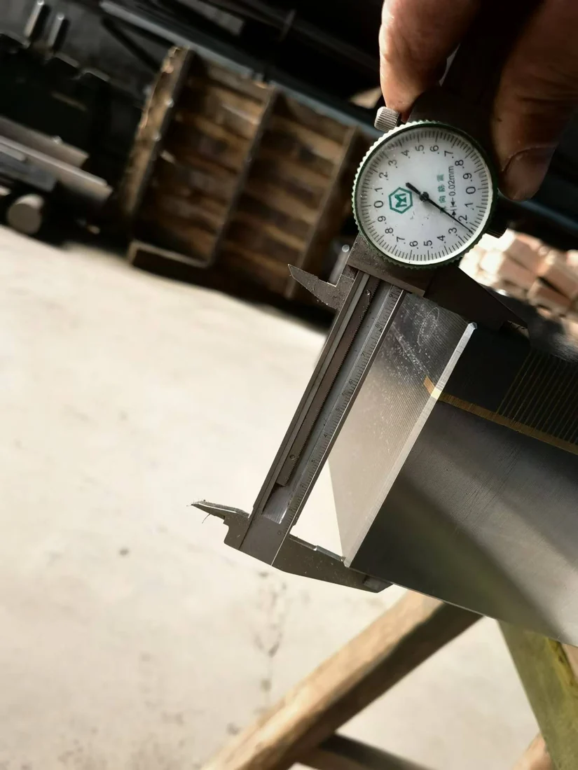
Do not infer permitted spindle speed or safe retention from nominal magnetic force.
Fit, concentric location and interfaces
Holding condition with the actual workpiece
Speed, balance and machine requirements
Unloading and residual magnetism
Engineering for turning of ferromagnetic circular parts begins with a purpose-engineered circular holding face and mechanical location. Workpiece geometry and actual machine travel define the fixture outline; the magnetic pole arrangement must then be evaluated within that structure.
Drawing, material and machine details
Part and process feasibility
Holding structure and selection
Interface and acceptance criteria
Confirmed parts and components
Assembly, surface work and checks
Protective packing and documentation
Use, maintenance and questions
Answers to practical turning of ferromagnetic circular parts fixture questions, including material compatibility, operating limits and the information needed to assess the setup.
No. Rotating fixtures require specific engineering for speed, retention, mass, balance and failure behavior. A surface-grinding chuck is not automatically safe on a spindle.
Sometimes, when an engineered circular contact arrangement and positive retention suit the ring geometry and machine conditions.
Share part drawing and weight, machine/spindle details, maximum RPM, cutting loads, locating method and the proposed safety concept.
Ask about a fixture for turning of ferromagnetic circular parts by sharing a representative workpiece and its most demanding machining condition. We can discuss whether magnetic workholding is practical before defining a specific design.