INDUSTRIES / PRECISION PARTS MANUFACTURING

Magnetic Workholding Solutions for Precision Parts Manufacturing

Explore magnetic workholding for precision parts manufacturing, focusing on suitable ferromagnetic parts such as small tool steel blocks, thin plates and multi-part workholding fixtures. MAGWORK supports drawing-based fixture discussion for real machining conditions, not claims of universal compatibility or completed industry projects.

Explore Application Concepts ↘
APPLICATION-LED ENGINEERING

Where Magnetic Chucks Fit Precision Parts Manufacturing Manufacturing

Precision component production uses an assortment of workpieces, not a single magnetic-chuck standard. This page concentrates on ferromagnetic tooling and steel components where an open working face is valuable. Each example explains the machining task and the fixture decision that must be checked first.

We start with your drawings, grade, workpiece geometry, operation and machine. For suitable ferrous contact surfaces, an engineered magnetic fixture may help improve tool access. We assess whether support, locating stops and expected machining loads allow that approach before discussing a particular chuck technology.

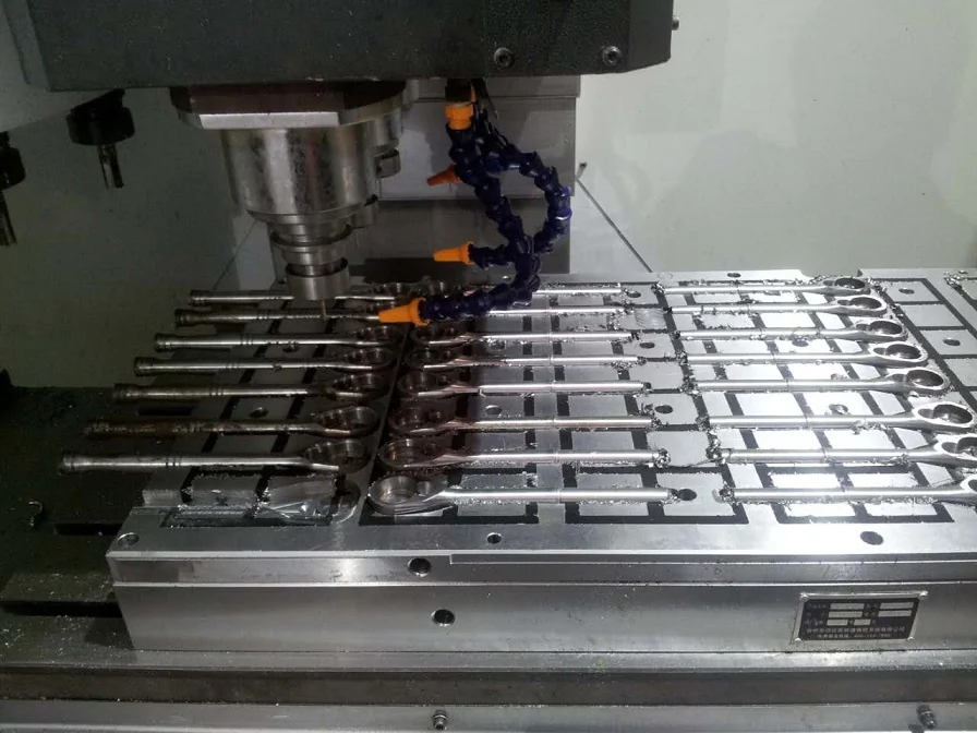
A series of similar steel components held during machining
Illustrative industrial image. No completed customer project or performance result is implied.
WORKPIECES & APPLICATION CONCEPTS

Precision Parts Manufacturing Magnetic Workholding Applications

The following are application concepts for precision component production, not claims of completed customer projects. Compare the geometry and process of each part with your own drawing before asking for a configuration.

01 / SMALL STEEL BLOCKS

Milling small precision steel blocks

Machining small steel blocks requires repeatable positioning without covers over key faces. The smallest batch size and contact footprint determine suitability.

Shaped metal component on a round magnetic fixtureA series of similar steel components held during machining

Free up the accessible machining faces

Combine suitable magnetic pole distribution with mechanical stops for milling loads.

For this precision parts manufacturing concept, the final drawing should identify usable magnetic contact, locating references and any nonmagnetic zones. Engineering checks: Smallest part, contact surface and lateral load. The proposal should state the fixture limits, proposed inspection scope and any conditions that require a mechanical alternative. Check the proposed fixture against the actual workpiece and cutting conditions before production.

WORKPIECESTool-steel plates, die components and hardened steel inserts
FIXTURE CONCEPTMagnetic holding face with tailored locating stops and local supports
CHECK FIRSTMaterial, contact footprint, machining force, cutter access and relief areas
VERIFYPosition repeatability, finished dimensions and holding conditions
02 / THIN STEEL PARTS

Drilling repeatable part-hole patterns

Multi-hole plates need space for every drill breakthrough while still holding securely. Narrow webs between holes limit available magnetic area.

Surface grinding a flat steel workpieceIllustration of a thin steel plate supported on a magnetic chuck

Treat deformation as a setup variable

Confirm the hole map, use relief channels and verify loading sequence.

For this precision parts manufacturing concept, the final drawing should identify usable magnetic contact, locating references and any nonmagnetic zones. Engineering checks: Part thickness, pole pitch and release deflection. The proposal should state the fixture limits, proposed inspection scope and any conditions that require a mechanical alternative. Check the proposed fixture against the actual workpiece and cutting conditions before production.

WORKPIECESFerrous tooling plates and production fixture bases
DESIGN FOCUSHole access, repeat loading and support under drilling locations
CHECK FIRSTDrill thrust, through-hole clearance, chip path and stop position
VERIFYSetup repeatability and agreed workpiece inspection criteria
03 / MULTI-PART FIXTURES

Grinding thin and narrow precision components

Thin ferrous blanks may respond to a fine-pole chuck, but local air gaps or uneven thickness can affect force.

Machining a hole pattern in steel workpieces on magnetic chucksSteel tooling components positioned on a square-pole magnetic chuck

One fixture only when the envelope truly fits

Focus on workface flatness, stable support and a consistent cleaning and measurement routine.

For this precision parts manufacturing concept, the final drawing should identify usable magnetic contact, locating references and any nonmagnetic zones. Engineering checks: Part-family envelope, stop positions and throughput. The proposal should state the fixture limits, proposed inspection scope and any conditions that require a mechanical alternative. Check the proposed fixture against the actual workpiece and cutting conditions before production.

WORKPIECESFlat ferrous components, tool inserts and steel plates
DESIGN FOCUSSupport distribution and appropriate magnetic pole layout
CHECK FIRSTThickness, magnetic material properties and ground area
VERIFYFlatness, surface condition and demagnetization where needed
CUSTOM MAGNETIC FIXTURE ENGINEERING

Custom Magnetic Fixture Engineering for Precision Parts Manufacturing

For precision component production, a custom magnetic fixture starts with a specific contact face and machine interface. Pole layout, support blocks, stop locations and clearance should be chosen from the actual part geometry. Standard chuck dimensions are only a starting reference.

Confirm material response before specifying magnetic holding. In small batches of steel components, the relevant workpiece is a ferromagnetic tooling component; nonmagnetic finished parts may instead require a dedicated adapter or conventional mechanical fixture.

Workshop floor with machine tools and prepared magnetic chuck components
ENGINEERING & PRODUCTION CAPABILITY

Magnetic Chuck Manufacturing and Testing Capability for Precision Parts Manufacturing

The manufacturing gallery shows general workholding production stages: machined bodies, pole components, assembly, finishing and inspection. For a precision component production order, the agreed mounting dimensions and acceptance points determine what must be checked on the finished chuck.

01 / 06 · ENGINEERING DESIGN

Designed around the workpiece

For small steel blocks and thin blanks, the engineering review connects magnetic pole placement to the actual machining and machine mounting. Reference edges, stops and support zones should be visible on the approved fixture drawing.

Workpiece reviewContact & pole layoutDesign confirmation

Production images illustrate body machining, assembly, finishing and inspection. Confirm any industry-specific process or performance claim against records for the supplied fixture.

PROJECT SUPPORT / PRECISION PARTS MANUFACTURING

Engineering and After-Sales Support for Precision Parts Manufacturing Fixtures

Technical support for precision component production projects concentrates on drawing coordination, installation interfaces and practical operating guidance. Project documents should identify the selected chuck configuration, machine mounting, operating controls if applicable, and agreed checks before shipment.

01

Application & feasibility review

Before support can recommend a fixture for fine details and changing holding footprints, confirm material and usable contact face. Identify the machining load direction and any installation restriction that may affect the proposed setup.

02

Drawing & configuration coordination

Technical coordination focuses on small-part pole engagement and clean stops. Electrical controls are considered only when the selected magnetic technology uses a controller.

03

Inspection & delivery documents

Agree on acceptance evidence relevant to thin blank flatness and inspection repeatability, including the dimensions and functional tests that the actual fixture needs, rather than a generic test checklist.

04

Setup & after-sales communication

After delivery, installation support should address quick repeat setup without obstructing critical surfaces; maintenance advice must follow the supplied magnetic system and its operating method.

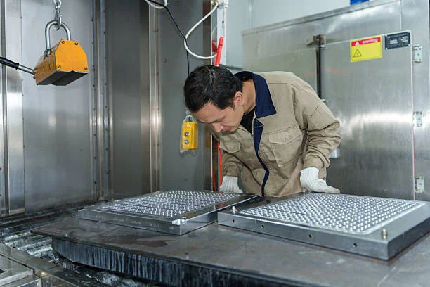
Operator checking magnetic chuck plates on a machine tableENGINEERING REVIEW → PRODUCTION → TECHNICAL SUPPORT
PRECISION PARTS MANUFACTURING / FAQ

Precision Parts Manufacturing Magnetic Workholding FAQs

These answers clarify material suitability, application limits and what to confirm when evaluating a magnetic fixture for precision component production.

Can one magnetic chuck hold several component sizes?

It depends on the minimum usable contact area, locating positions, supports and machining forces across the complete part family. In precision parts manufacturing, confirm the steel grade, real contact face and fixture clearance from the actual drawing. Do not present an illustrative application as a proven customer result.
Will a magnetic chuck eliminate distortion?

Not automatically. Thin parts can distort for several reasons. Workpiece thickness, grinding method, contact and release need review. In precision parts manufacturing, confirm the steel grade, real contact face and fixture clearance from the actual drawing. Do not present an illustrative application as a proven customer result.

Can magnetic workholding help multi-face access?

It can reduce obstructing clamps for selected ferrous parts, but the setup must still provide stable location and safe support. In precision parts manufacturing, confirm the steel grade, real contact face and fixture clearance from the actual drawing. Do not present an illustrative application as a proven customer result.

Are small precision parts difficult to hold magnetically?

They can be. Limited contact area and magnetic pole geometry make application-specific testing important. In precision parts manufacturing, confirm the steel grade, real contact face and fixture clearance from the actual drawing. Do not present an illustrative application as a proven customer result.

What dimensions should I submit?

Include minimum and maximum part sizes, steel grade, contact face, machining sequence and tolerance requirements. In precision parts manufacturing, confirm the steel grade, real contact face and fixture clearance from the actual drawing. Do not present an illustrative application as a proven customer result.

PRECISION PARTS MANUFACTURING / TECHNICAL INQUIRY

Request a Custom Magnetic Fixture for Precision Parts Manufacturing

For a precision component production workholding review, provide the workpiece drawing and identify the machining face that must stay accessible. Add the machine model and material grade so the proposed fixture can be evaluated against a real task.

Request an application review

For the initial review, identify the representative workpiece and small-part pole engagement and clean stops. Attach its drawing and machine interface details.

The project examples above are illustrative, not verified customer case studies. Replace reference photos and details with approved material before publishing.