ELECTRO-PERMANENT CHUCK / ENGINEERED WORKHOLDING

Electro-Permanent Magnetic Chucks
One Pulse. A Smarter Fixture.

Pulse-switched magnetic workholding for machining systems and automated fixture integration.

Find Your Configuration ↗
Pulse switchingController & CNC integrationModular workholding
01 / PERMANENT MAGNETIC CHUCK

Electro-Permanent Magnetic Chucks for Precision Workholding

Pulse-switched magnetic workholding for machining systems and automated fixture integration.

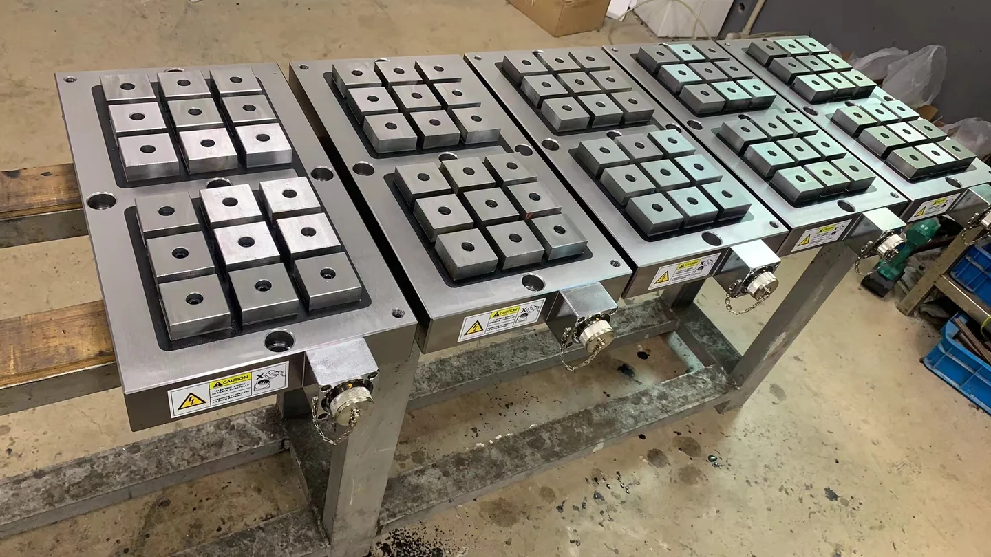
Electro-permanent chuck with a closely spaced square pole face and controller
Holding conceptA magnetic circuit provides holding force through a suitable ferromagnetic workpiece.
02 / HOW IT WORKS

How Does an Electro-Permanent Magnetic Chuck Work?

An electro-permanent design uses a controlled electrical pulse to change magnetic state; holding does not require continuous energization after switching. Release permission and state feedback are essential in automated setups.

Check switching sequence, controller interface, feedback and mechanical stops for each machining operation.

01Pulse switchingThe part must be sufficiently magnetic; many non-ferrous materials cannot be held directly.
02Feedback & interlockFlatness, surface condition and effective pole coverage affect real holding performance.
03Contact & supportCutting loads and lift or sliding forces must be checked before selection.
ENGINEERING FEATURE / PULSE CONTROL

Electro-Permanent Magnetic Chuck Switching and Machine Interlocks

The controller should only permit a release under defined machine conditions. Confirm PLC interfaces, clamp-state signals, pulse supply and procedures for a power interruption.
01 / CNC OR PLCSwitching requestCommand from approved machine logic
→
02 / CONTROLLERPulse & switchingDrive the magnetic state transition
→
03 / FEEDBACKState confirmationCheck the actual control signal
→
04 / MACHINECycle permissionInterlocks based on verified conditions
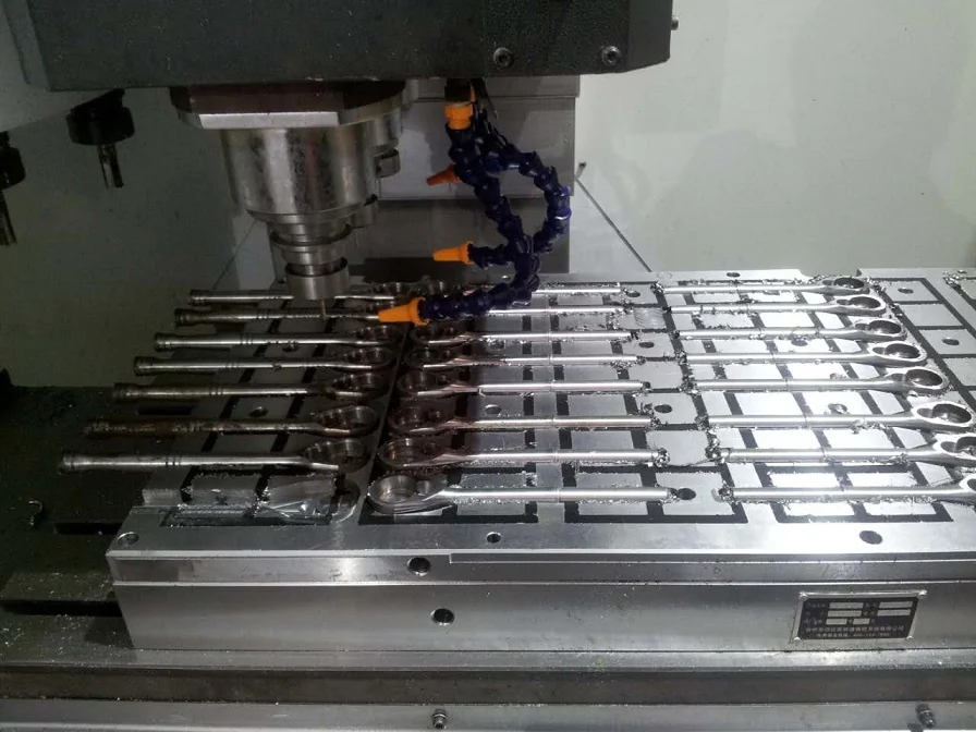
A series of similar steel components held during machining
Magnetic holding is only part of the automation system.

Mechanical stops, contact conditions and safety logic also determine suitability.

03 / PERMANENT CHUCK SELECTION

How to Select an Electro-Permanent Magnetic Chuck

Start with ferromagnetic contact area, required switching arrangement and machining loads. Then review pole geometry, control interfaces and whether a single chuck or multiple zones are appropriate.

FIXTURE & AUTOMATION REVIEW01 / 03

Fine-pole grinding configuration

Start with part geometry, holding contact and process forces. The final solution still needs engineering review.

Electro-permanent chuck with a closely spaced square pole face and controller
Recommended product
  • Fine pole layout
  • Supporting contact surface
  • Release and residual magnetism

Illustrative selection guidance only. It does not confirm magnetic holding force, safety or compatibility without workpiece data and application testing.

Electro-permanent fixture configurations

Representative configurations for engineering review. Dimensions and performance must be confirmed for the real workpiece.

10 configurationsConcept configurations · final specifications confirmed by engineering review
Electro-permanent chuck with a closely spaced square pole face and controllerCONCEPT PM-01
Precision workholding

Fine-Pole Modular Face

Pole layout
Fine / micro pole concept
Applications
Grinding · Inspection
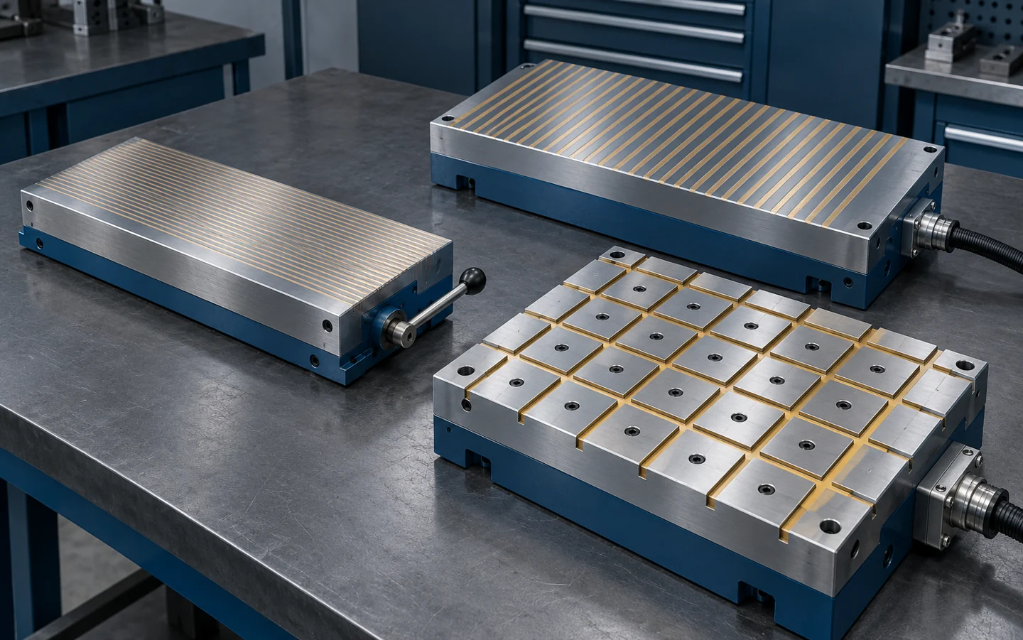
Rectangular electro-permanent magnetic chuck with square polesCONCEPT PM-02
Multi-part holding

Rectangular Module

Pole layout
Standard pole concept
Applications
Grinding · Inspection
Modular magnetic chuck plates and pole extensionsCONCEPT PM-03
Small part access

Compact Pole Extensions

Pole layout
Fine / micro pole concept
Applications
Grinding · Inspection
Long electro-permanent magnetic chuck with square polesCONCEPT PM-04
Large machine envelope

Long-Table Modular System

Pole layout
Standard pole concept
Applications
Grinding · Inspection
Steel tooling components positioned on a square-pole magnetic chuckCONCEPT PM-05
Stops and support

High-Support Fixture

Pole layout
Standard pole concept
Applications
Grinding · Milling
Round electro-permanent magnetic chuck with radial pole layoutCONCEPT PM-06
Round workpieces

Circular EPM System

Pole layout
Circular pole concept
Applications
Grinding · Inspection
Magnetic fixture mounted on a CNC rotary machine tableCONCEPT PM-07
Integrated machining

Rotary Interface Fixture

Pole layout
Circular pole concept
Applications
Grinding · Inspection
Rectangular electro-permanent magnetic chuck with square polesCONCEPT PM-08
Height constraint

Low-Profile Pole Modules

Pole layout
Fine / micro pole concept
Applications
Grinding · Inspection
Modular magnetic chuck plates and pole extensionsCONCEPT PM-09
Automated cell

Multi-Zone Fixture

Pole layout
Custom pole arrangement
Applications
Grinding · Inspection
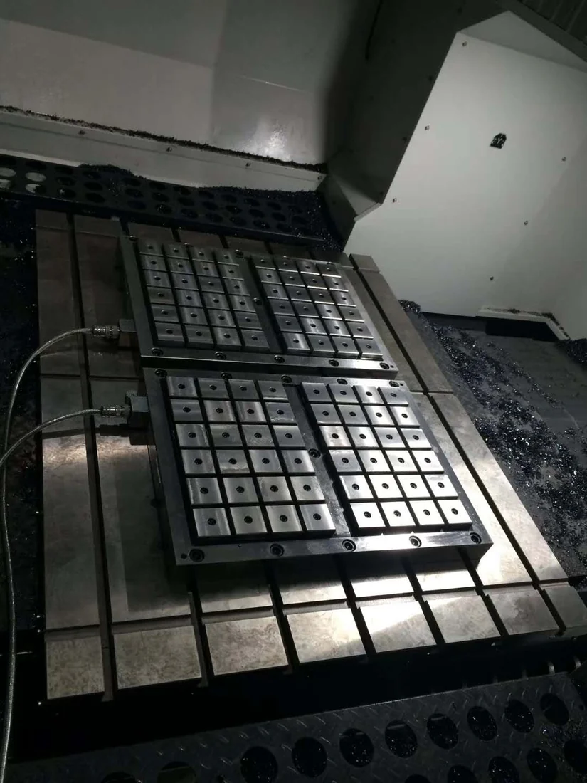
Magnetic chuck installed on a CNC machine tableCONCEPT PM-10
Signals and feedback

CNC-Integrated Custom Fixture

Pole layout
Custom pole arrangement
Applications
Grinding · Inspection · Milling
YOUR CURRENT STARTING POINTCustom design is always available

Share your drawing if none of these starting configurations fits your machine or part.
These are illustrative configuration families, not published product specifications. Actual models, dimensional limits and measured holding force must be confirmed from verified technical documentation. Magnetic holding suitability requires engineering review.
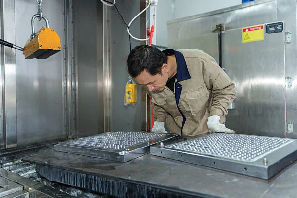
Operator checking magnetic chuck plates on a machine tableAPPLICATION-LED ENGINEERING
04 / CUSTOM ENGINEERING

Design the fixture.
Connect the machine.

Engineer magnetic modules, pole extensions, controller signals, sensors, supports and the CNC/PLC interface as one fixture system.

01Magnetic module layoutArrange modules and extensions around the workpiece.
02Switching controlDefine magnetize / demagnetize signals.
03Machine interfaceConfirm CNC/PLC interlock and feedback logic.
04Fixture verificationReview lateral loads, stops and holding tests.
05 / APPLICATION REFERENCES

Every fixture.
A different integration.

For mold bases and steel fixtures, tool access and locating supports may be more decisive than the magnet size. Machine-specific setups should account for lateral cutting force and controlled release.
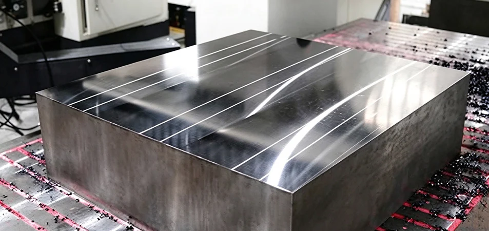
Steel block with its upper machining face clear of top clamps
APPLICATION / CNC MILLING CELL

Mold base machining

Pulse switching, support stops and cutting forces.

Engineer magnetic modules, pole extensions, controller signals, sensors, supports and the CNC/PLC interface as one fixture system.

ENGINEERING FOCUSEngineer magnetic modules, pole extensions, controller signals, sensors, supports and the CNC/PLC interface as one fixture system.

Magnetization and demagnetization sequences, controller feedback, interface signals, contact force and machine interlocks.

PART TYPEMold base machining
MAIN CHALLENGEPulse switching, support stops and cutting forces.
WHAT TO CHECKMagnetization and demagnetization sequences, controller feedback, interface signals, contact force and machine interlocks.
Case scenariosClick a case to update the left display
Steel block with its upper machining face clear of top clampsCNC MILLING CELLMold base machiningPulse switching, support stops and cutting forces.
A series of similar steel components held during machiningMULTI-PART FIXTUREBatch workpiecesPole modules, loading sequence and repeatability.
Magnetic fixture mounted on a CNC rotary machine tableROBOTIC LOADINGAutomated machining cellHandshake, feedback and fail-safe interlocks.
Modular magnetic chuck plates and pole extensionsCUSTOM MODULAR FIXTUREIrregular steel componentsEngineered contact, machine integration and verification.
06 / ORDER & PROJECT PROCESS

From your drawing
to a ready-to-use chuck.

Project approval should capture pulse-control conditions, magnetic zones, fixture dimensions and operating signals before manufacture. Confirm the drawing and inspection method together.
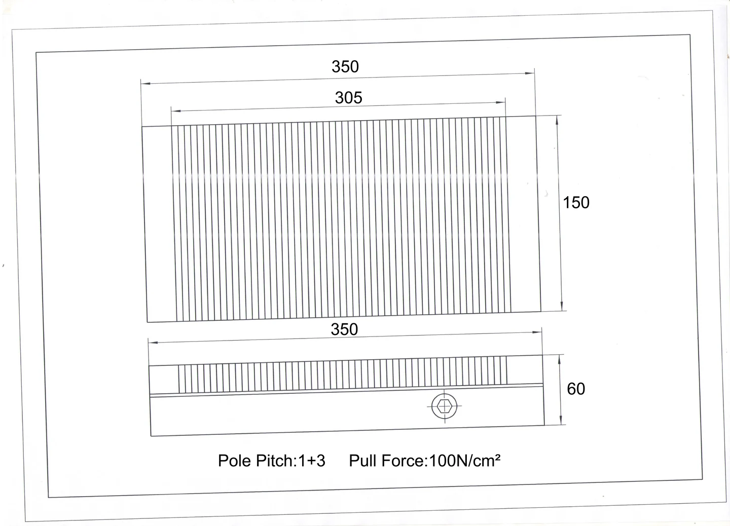
Dimensioned magnetic chuck working-face and mounting drawing
01

Share Process Data

Send the workpiece geometry, material, machine model and machining operation.

Steel workpiece contacting a fine pole magnetic chuck
02

Integration Review

Check magnetic suitability, contact area, force direction and part constraints.

Modular magnetic chuck plates and pole extensions
03

Fixture Architecture

Review chuck layout, mounting method, working face and support concept.

Dimensioned magnetic chuck working-face and mounting drawing
04

Interface Approval

Confirm dimensions, structure details and the final technical requirements.
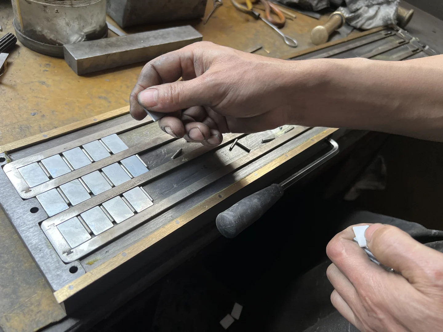
Fitting pole components during magnetic chuck assembly
05

Module & Controller Build

Machine the key parts, assemble the magnetic structure and prepare for inspection.
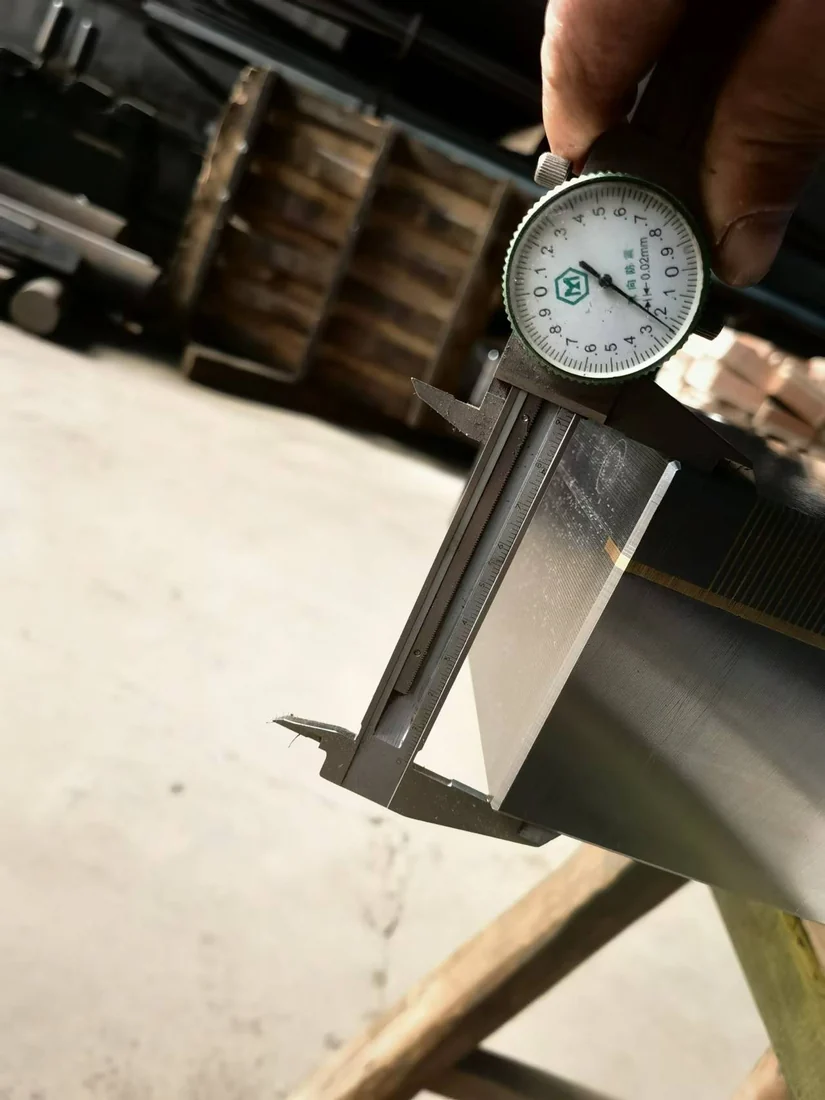
Dial caliper checking a magnetic chuck dimension
06

Pulse & Interlock Testing

Check dimensions, appearance, function and agreed magnetic testing conditions.
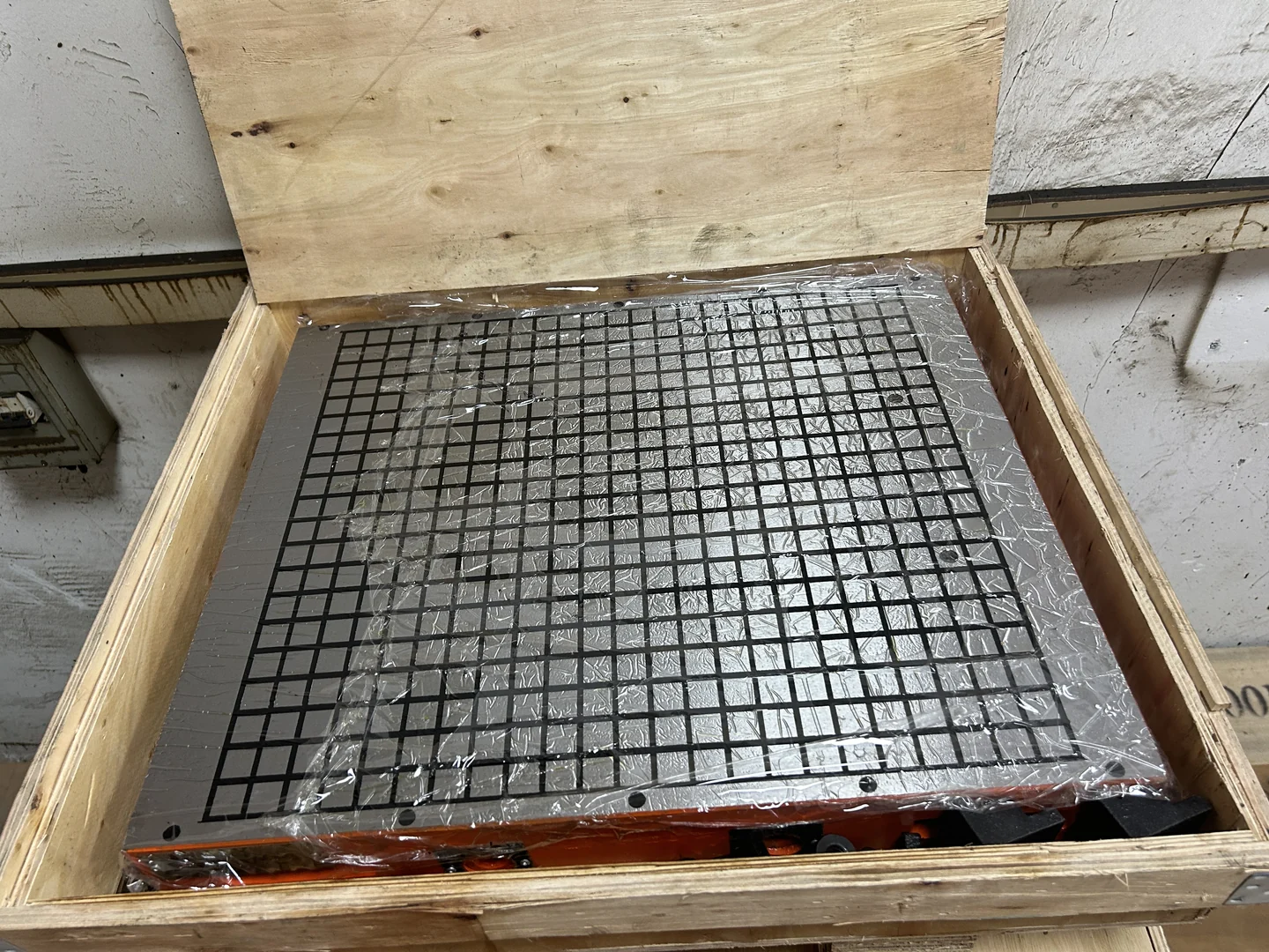
Magnetic chuck protected in a wooden shipping crate
07

Pack & Document

Protect the working face, prepare labels and include agreed reports or documents.
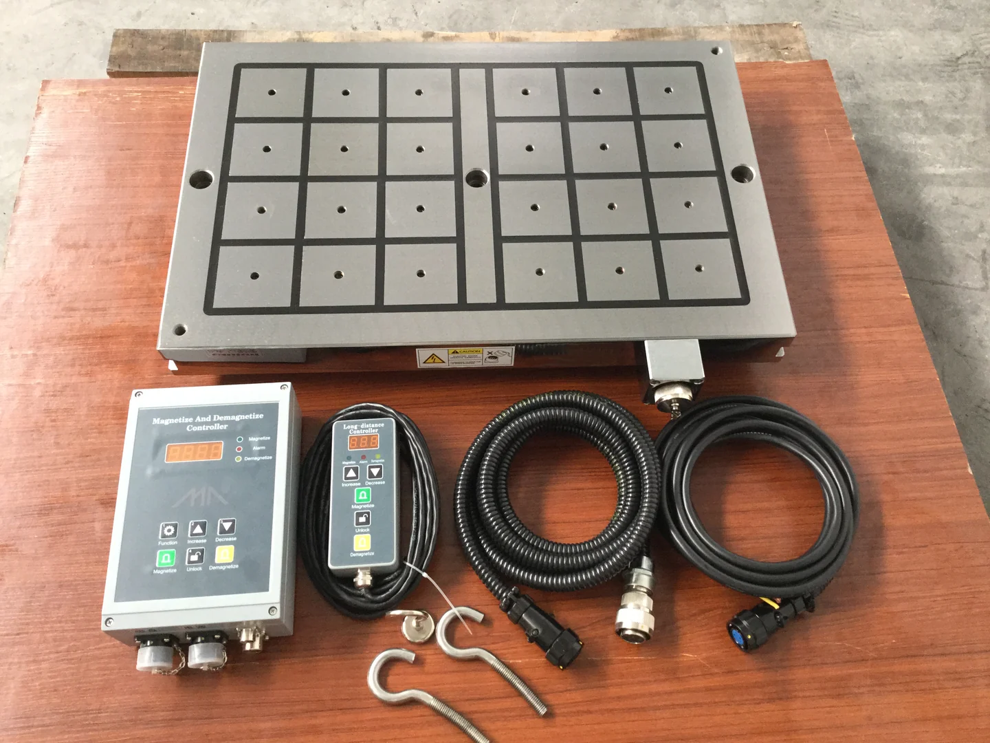
Electro-permanent magnetic chuck with controller, pendant and cables
08

Launch & Support

Arrange shipment and stay available for installation, operation and follow-up support.

START WITH A DRAWING, EVEN IF YOU HAVE NOT CHOSEN A CHUCK MODEL.
07 / ENGINEERING & TECHNICAL SUPPORT
Dimensioned magnetic chuck working-face and mounting drawingAPPLICATION-LED SUPPORT

Support from the fixture
to the control cabinet.

Support focuses on controller integration, clamp/release procedures and post-installation diagnostics. Operating safety depends on the machine interlocks as well as the magnetic plate.

Machine Handshake

Review PLC/CNC request, permission and confirmation signals.

Cycle Programming

Define magnetization and release workflow.

Fixture & Stops

Coordinate module positions and mechanical support.

Commissioning Support

Review start-up checks and documentation.

08 / WORKSHOP & EQUIPMENT

From pole modules
to integrated fixtures.

Manufacture may involve body and pole machining, preparation of permanent magnets and coil components, controlled assembly, sealing, final surface grinding and switching tests.

Workshop floor with machine tools and prepared magnetic chuck components
WORKSHOP OVERVIEWModular Fixture Workshop
Steel block with its upper machining face clear of top clamps
Precision Pole MachiningChuck body and mounting features
Surface grinding a steel workpiece on a magnetic chuck
Face FinishingWorking-face finishing
Fitting pole components during magnetic chuck assembly
Magnetic Module AssemblyMagnetic circuit and mechanism
Dial caliper checking a magnetic chuck dimension
Pulse-Control ValidationDimensions and functional checks
Dimensioned magnetic chuck working-face and mounting drawing
CNC Interface ReviewDesign interface and manufacturing support

Have a special chuck size, mounting interface or holding layout? We can review your drawing before defining the production approach.

09 / TESTING & DOCUMENTATION

Watch the test.
Review the records.

Verification should include switched-state behavior, magnetic performance, controller feedback, working-face geometry and the agreed release conditions. Test records must identify the actual unit.
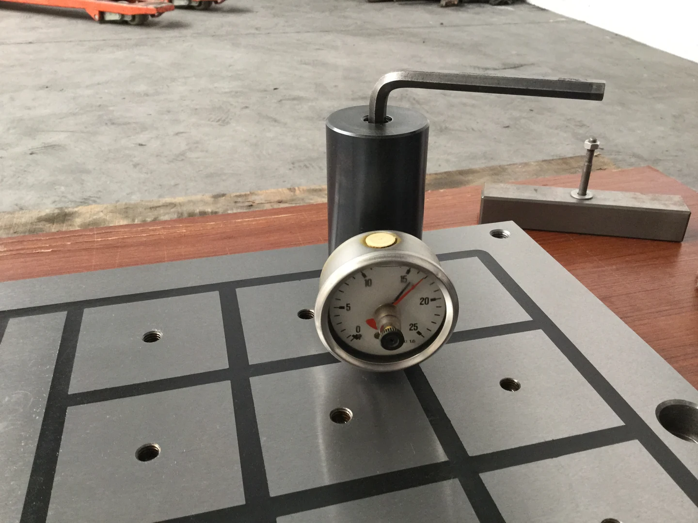
Pull-force gauge and test piece on a magnetic chuck face
VIDEO / TESTING DEMONSTRATION

Electro-Permanent Chuck Verification

Magnetization and demagnetization sequences, controller feedback, interface signals, contact force and machine interlocks.

Reports & Certifications4 document positions
01PULSE SEQUENCEDOCUMENT SLOT

Holding Force Test

Test setup, conditions and results.

02FEEDBACK CHECKDOCUMENT SLOT

Magnetic Field Check

Measurement method and locations.

03HOLDING TESTDOCUMENT SLOT

Dimensional Inspection

Critical sizes and surface checks.

04INTERFACE REPORTDOCUMENT SLOT

Certificate / QC Record

Insert an applicable issued document.

Template only: upload real MP4 footage and replace each report slot with a verified, publishable document. No certificate or measurement result is implied by these placeholders.

11 / CARE & MAINTENANCE

Keep switching reliable.
Protect your process.

Inspect controller cables, magnetic face, locating supports and switching indicators. Follow the approved clamp/release sequence and service guidance for the supplied system.

01Clean contact facesRemove chips and check pole extensions.
02Verify status signalsCheck controller feedback and indicators.
03Review interlocksConfirm machine permissions and sequence.
04Check switching behaviorFollow approved magnetize/release tests.
Hand finishing a magnetic chuck component at a workbench
Routine inspection helps keep holding performance stable.Use the actual operating guide for the installed chuck model and review cleaning, mounting and release conditions regularly.
12 / FREQUENTLY ASKED QUESTIONS

Electro-Permanent Magnetic Chuck FAQs

These questions address power-free holding after activation, safe release, machine integration and component suitability.

01Are you a manufacturer or a trading company?+

MAGWORK supports technical selection, project coordination and product inspection in cooperation with manufacturing partners. The scope of manufacture and service should be confirmed for each order.

Can electro-permanent chucks be made to a drawing?

Engineer magnetic modules, pole extensions, controller signals, sensors, supports and the CNC/PLC interface as one fixture system.

03How long does production and delivery take?+

Timing depends on design approval, magnet and controller availability, body machining, sealing, system testing and shipping. Confirm lead time only after the scope and required interfaces are agreed.

04What testing and reports can you provide?+

Typical agreed checks can include pole-face geometry, magnetic activation and release, controller indications, insulation where applicable and holding tests with stated contact conditions. The tests should match the delivered configuration.

Does an electro-permanent chuck need continuous electricity?

Magnetization and demagnetization sequences, controller feedback, interface signals, contact force and machine interlocks. Specific design and operating limits need review against the actual machine and workpiece.

Is the workpiece safe during a power failure?

Magnetization and demagnetization sequences, controller feedback, interface signals, contact force and machine interlocks. Specific design and operating limits need review against the actual machine and workpiece.

What must be checked before CNC integration?

Magnetization and demagnetization sequences, controller feedback, interface signals, contact force and machine interlocks. Specific design and operating limits need review against the actual machine and workpiece.

Have an unusual part or machine interface?
YOUR PART. YOUR MACHINE. YOUR SOLUTION.

Discuss a Custom Electro-Permanent Magnetic Chuck

For an electro-permanent fixture proposal, start with the steel workpiece, machine model and intended switching and safety sequence.