CONTACT
Real contact area
Review usable ferromagnetic surface, air gaps and part seating.
Magnetic workholding for CNC milling is useful only when the workpiece has sufficient ferromagnetic contact and the fixture can manage the machining load. This page focuses on lateral cutting force, cutter engagement and workpiece movement, rather than a single catalog holding-force rating.
Engineering for CNC milling begins with locating stops and positive side-load restraint. Workpiece geometry and actual machine travel define the fixture outline; the magnetic pole arrangement must then be evaluated within that structure.
Review usable ferromagnetic surface, air gaps and part seating.
Mechanical stops may be needed; magnetic holding should not be treated as sufficient by default.
Plan open faces and cutter approach without tool-fixture collisions.
Match fixture height, footprint and control needs to the machine.
Engineering for CNC milling begins with locating stops and positive side-load restraint. Workpiece geometry and actual machine travel define the fixture outline; the magnetic pole arrangement must then be evaluated within that structure.
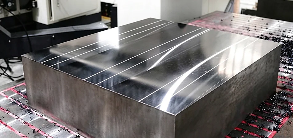
Potential setups for suitable contact and controlled cutting conditions. For CNC milling, confirm support, magnetic contact and machine access against the drawing before treating this as a usable configuration.

Review pole extension, stop placement and practical support. For CNC milling, confirm support, magnetic contact and machine access against the drawing before treating this as a usable configuration.
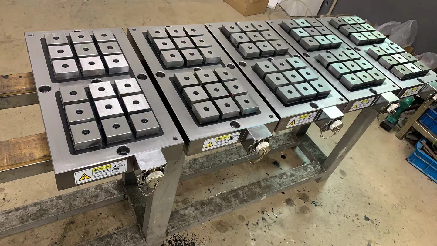
Review magnetic plate size, support blocks and mounting holes. For CNC milling, confirm support, magnetic contact and machine access against the drawing before treating this as a usable configuration.
For CNC milling, common workpiece categories include steel mold bases, mounting plates and block parts. They do not all need the same magnetic face. Each setup should account for its own contact footprint, support requirements and machining envelope.
A proposed layout can describe magnetic poles, mechanical locating stops, workpiece seating, clearance and electrical connections where relevant. Final checks must follow the agreed operating conditions.
Match workpiece contact
Manage lateral force
Protect cutter access
Fit machine table
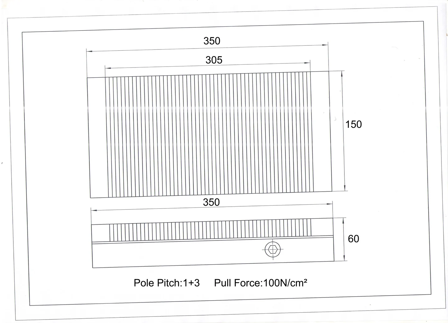
These examples show where CNC milling magnetic workholding can be considered for steel fixture plates, tooling blocks and supported mold components. They are application concepts, not claims about completed customer projects or measured production gains. Each layout requires its own force, contact and safety review.
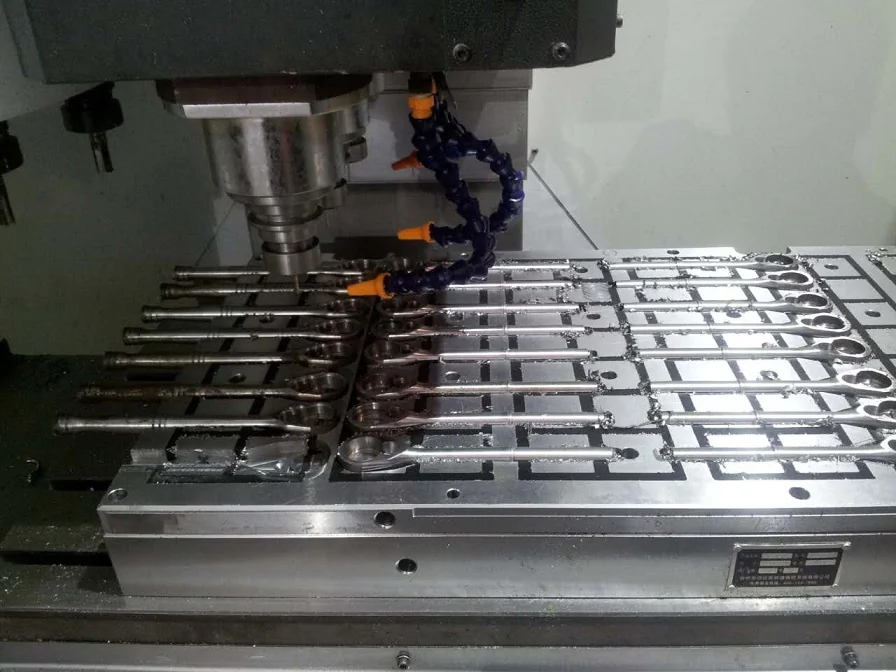
Consider the open machining faces, contact geometry and positive stops. For CNC milling, confirm support, magnetic contact and machine access against the drawing before treating this as a usable configuration.
Large faces, cutting load direction and machine height. For CNC milling, confirm support, magnetic contact and machine access against the drawing before treating this as a usable configuration.
Tool and fixture clearance around the part.
Coordinate loading, positioning and activation where appropriate. For CNC milling, confirm support, magnetic contact and machine access against the drawing before treating this as a usable configuration.
For CNC milling, common workpiece categories include steel mold bases, mounting plates and block parts. They do not all need the same magnetic face. Each setup should account for its own contact footprint, support requirements and machining envelope.
An interrupted milling cut can push sideways. Evaluate the expected lateral load and arrange positive locating stops instead of treating magnetic attraction as a complete restraint.
Ribs, pockets and irregular cast surfaces limit magnetic contact. Choose supports that avoid rocking and do not block the tool path.
Check cutter diameter, approach direction and required edge access. The fixture should leave room for chips, coolant and safe retract movement.
For a batch of similar parts, locate from stable datums and plan unloading or reloading without moving the reference stops.
APPLICATION REVIEW / TECHNICAL REFERENCEA usable CNC milling fixture drawing should locate the workpiece reference edges, magnetic contact surface, mounting holes and any relief areas. It should also call out tool access, chip evacuation and milling travel, so the fixture does not interfere with the operation.
The part may contact only at pads or ribs. A customized pole arrangement, raised supports or a different fixture type may be needed.
Magnetic holding can reduce obstruction by top clamps, but cutter reach, part overhang, support points and locating stops remain essential.
Select the magnetic technology after defining lateral cutting force, cutter engagement and workpiece movement. Compare permanent, electromagnetic and electro-permanent systems by their switching method, control needs, pole design and application limits—not by keyword or chuck size alone.
Agree on table size, T-slot spacing, base height, fastening access and the available machine travel.
Define pole zones, support contact, side stops and any sacrificial clearance areas based on the actual machining plan.
Document dimensional inspection, operating sequence and any test method used to assess holding under the expected load directions.
Choose a different holding method when magnetic contact is too small, the part is nonmagnetic, or shear load, overturning and mechanical stops cannot be controlled. A mechanical restraint or completely different fixture may be safer than increasing the nominal magnet rating.
Useful to evaluate for side-loaded workpieces because stops can resist sideways movement while the magnetic face supplies downward retention.
Possible when underside pockets, chips or uneven weldments prevent broad contact. Support positions and pole engagement require specific design.
The fixture height, table mounting, tool travel and chip removal space must be assessed as one assembly.
For non-ferrous materials, unsuitable contact or excessive cutting load, a mechanical or hybrid fixture may be the safer direction.
Acceptance for CNC milling should address the installed setup, not just a nominal pull-off figure. In particular, verify machine interface, stop contact and secure holding under the agreed cut. Record the actual test conditions and compare them with the agreed application limits.
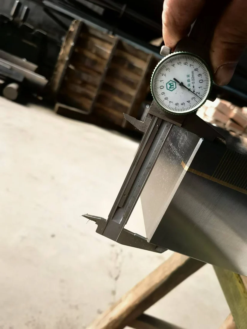
Fixture selection is followed by the applicable production and test plan.
Body, mounting hole and pole features
Assembly and switching per configuration
Surface geometry and contact face
Documented checks under agreed conditions
After choosing a provisional CNC milling fixture, confirm dimensions and acceptance points before production. The shipment should match the approved drawings, with available operating information for the actual magnetic system.
Drawing, material and machine details
Part and process feasibility
Holding structure and selection
Interface and acceptance criteria
Confirmed parts and components
Assembly, surface work and checks
Protective packing and documentation
Use, maintenance and questions
Answers to practical CNC milling fixture questions, including material compatibility, operating limits and the information needed to assess the setup.
No. High lateral loads, interrupted cuts and limited contact areas may require positive stops or another clamping method. Holding feasibility should be assessed for each toolpath.
Do not assume suitability from a pull-off-force rating. Estimate cutting force direction, contact footprint, stops and support, and validate the setup.
Provide workpiece drawing, ferromagnetic grade, cutter path, machine model, mounting dimensions, estimated forces and required clearances.
Engineering for CNC milling begins with locating stops and positive side-load restraint. Workpiece geometry and actual machine travel define the fixture outline; the magnetic pole arrangement must then be evaluated within that structure.