Plan how magnetic poles contact the part, including non-contact areas and surface features.
ABOUT MAGWORK / ENGINEERING & CUSTOMIZATION
Your workpiece. Our starting point.
Workpiece-driven magnetic fixture review, pole layout, stops, support and machine integration for industrial machining.
Discuss Your Project ↗ENGINEERING EVALUATION
From your drawing to a workholding concept.
Magnetic holding force alone is not enough to select a fixture. We review where the part contacts the chuck, where the tool must travel, and how machining forces act on the setup.
- Workpiece geometryMaterial grade, dimensions, underside flatness, contact footprint and part variability.
- Process loadsCutting or grinding direction, drill breakthrough, side forces and support conditions.
- Machine interfaceTable dimensions, T-slots, spindle reach, axis travel, coolant and chip path.
- Release and handlingHow the part is located, activated, removed and checked between operations.

DESIGN DECISIONS
What can be changed in a custom fixture?
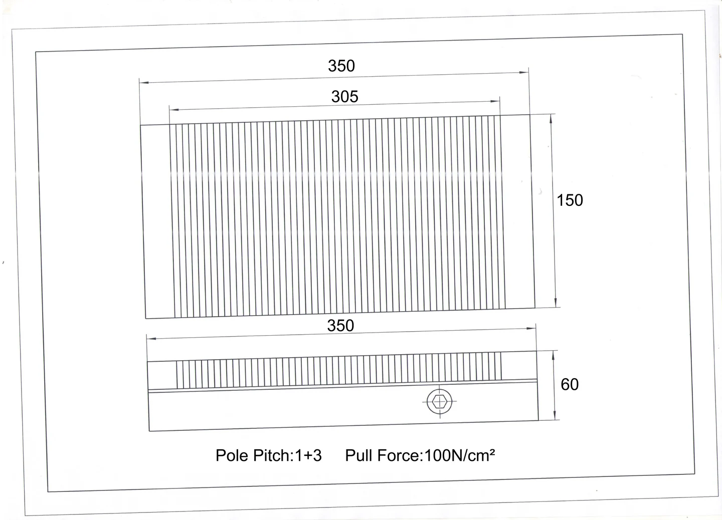
Add stops, side support or mechanical restraint where operating loads require more than magnetic holding.
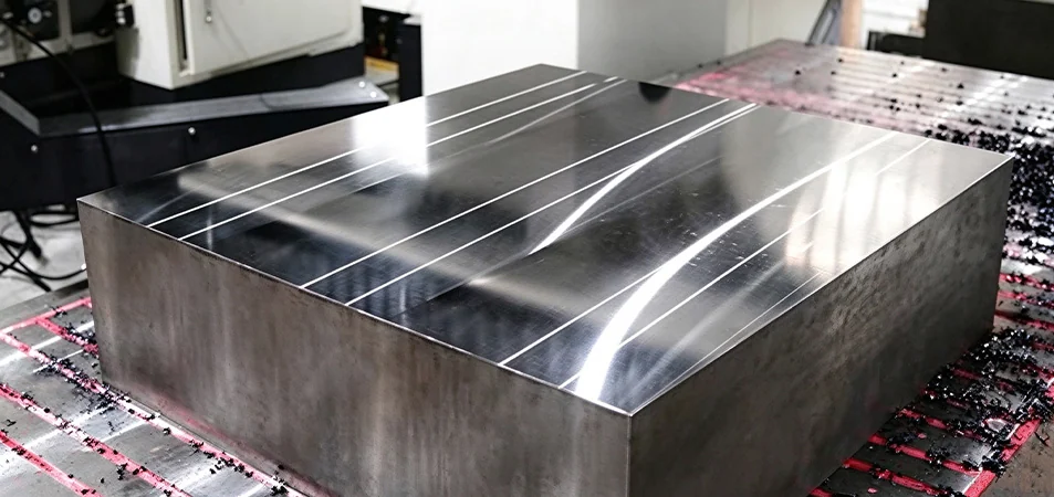
Leave safe paths for drill breakthrough, cutting tools and chip flow without damaging the chuck.
Match the chuck body, holes and orientation to the host machine.
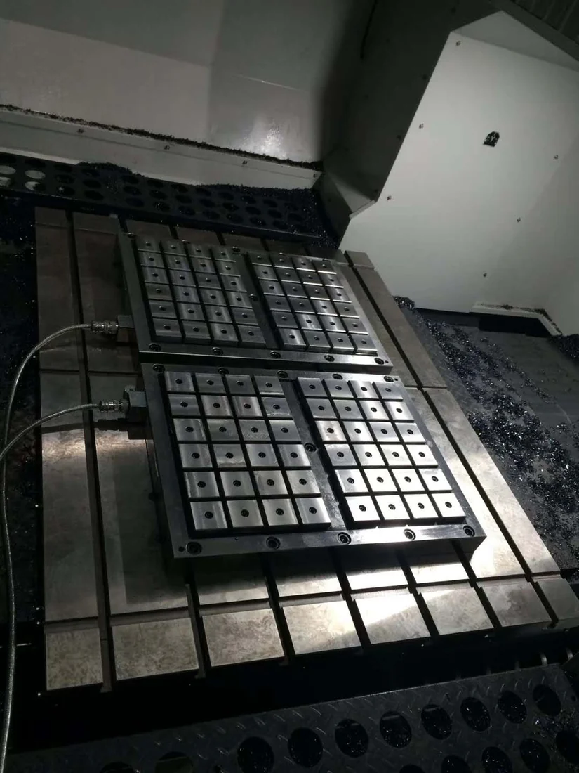
For powered chucks, review supply, switching, cables and controller integration.
Agree on dimensions and functional tests that can validate the delivered configuration.
DESIGN SHOWCASE
Different machines need different holding structures.

APPLICATION / DRILLING
Protect the working face around through-holes.
A hole map is reviewed alongside support points and chip evacuation. Relief zones and positioning stops can be considered where needed.
APPLICATION / MILLING
Plan for lateral cutting loads.
Contact area, machining direction and positive stops are considered together so the fixture is not chosen by a nominal magnetic rating alone.

APPLICATION / GRINDING
Support thin parts with care.
Pole pattern, material thickness and contact condition should be reviewed to control workpiece movement and reduce distortion risk.
WHAT YOU CAN PROVIDE
Send the information needed for a useful review.
Part drawing
2D / 3D part geometry and key dimensions.
Material & contact
Steel grade, thickness and working contact surface.
Machine & operation
Machine model, tool path and machining parameters.
Acceptance points
Required accuracy, setup method and any inspection criteria.

WORK WITH MAGWORK
Start with your workpiece and machine requirements.
Share a drawing, material, process and required interface. The discussion can then focus on a practical magnetic workholding direction and the checks that matter to your project.
Send Your Requirements ↗